To create an LCD, you take two pieces of polarized glass . A special polymer that creates microscopic grooves in the surface is rubbed on the side of the glass that does not have the polarizing film on it. The grooves must be in the same direction as the polarizing film. You then add a coating of nematic liquid crystals to one of the filters. The grooves will cause the first layer of molecules to align with the filter's orientation. Then add the second piece of glass with the polarizing film at a right angle to the first piece. Each successive layer of TN molecules will gradually twist until the uppermost layer is at a 90-degree angle to the bottom, matching the polarized glass filters.
As light strikes the first filter, it is polarized. The molecules in each layer then guide the light they receive to the next layer. As the light passes through the liquid crystal layers, the molecules also change the light's plane of vibration to match their own angle. When the light reaches the far side of the liquid crystal substance, it vibrates at the same angle as the final layer of molecules. If the final layer is matched up with the second polarized glass filter, then the light will pass through.
If we apply an electric charge to liquid crystal molecules, they untwist! When they straighten out, they change the angle of the light passing through them so that it no longer matches the angle of the top polarizing filter. Consequently, no light can pass through that area of the LCD, which makes that area darker than the surrounding areas.
Building Your
Own LCD
Building a simple LCD is easier than you think. Your start with the
sandwich of glass and liquid crystals described above and add two transparent
electrodes to it. For example, imagine that you want to create the simplest
possible LCD with just a single rectangular electrode on it. The layers
would look like this:
|
|
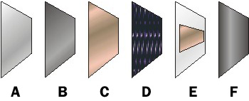
The LCD needed to do this job is very basic. It has a mirror (A ) in back, which makes it reflective. Then, we add a piece of glass ( B ) with a polarizing film on the bottom side, and a common electrode plane (C ) made of indium-tin oxide on top. A common electrode plane covers the entire area of the LCD. Above that is the layer of liquid crystal substance (D). Next comes another piece of glass (E) with an electrode in the shape of the rectangle on the bottom and, on top, another polarizing film (F), at a right angle to the first one.
The electrode is hooked up to a power source like a battery . When there is no current, light entering through the front of the LCD will simply hit the mirror and bounce right back out. But when the battery supplies current to the electrodes, the liquid crystals between the common-plane electrode and the electrode shaped like a rectangle untwist and block the light in that region from passing through. That makes the LCD show the rectangle as a black area.
Passive Matrix
Passive-matrix LCDs use a simple grid to supply the charge to a particular
pixel on the display. Creating the grid is quite a process! It starts with
two glass layers called substrates. One substrate is given columns
and the other is given rows made from a transparent conductive material. This
is usually indium-tin oxide. The rows or columns are connected to
integrated circuits that control when a charge is sent down a particular
column or row. The liquid crystal material is sandwiched between the two
glass substrates, and a polarizing film is added to the outer side of each
substrate. To turn on a pixel, the integrated circuit sends a charge down
the correct column of one substrate and a ground activated on the correct
row of the other. The row and column intersect at the designated pixel,
and that delivers the voltage to untwist the liquid crystals at that pixel.
The simplicity of the passive-matrix system is beautiful, but it has significant drawbacks, notably slow response time and imprecise voltage control . Response time refers to the LCD's ability to refresh the image displayed. The easiest way to observe slow response time in a passive-matrix LCD is to move the mouse pointer quickly from one side of the screen to the other. You will notice a series of "ghosts" following the pointer. Imprecise voltage control hinders the passive matrix's ability to influence only one pixel at a time. When voltage is applied to untwist one pixel, the pixels around it also partially untwist, which makes images appear fuzzy and lacking in contrast.
Active Matrix
Active-matrix LCDs depend on thin film transistors (TFT). Basically,
TFTs are tiny switching
transistors
and capacitors
. They are arranged in a matrix on a glass substrate. To address a particular
pixel, the proper row is switched on, and then a charge is sent down the
correct column. Since all of the other rows that the column intersects are
turned off, only the capacitor at the designated pixel receives a charge.
The capacitor is able to hold the charge until the next refresh cycle. And
if we carefully control the amount of voltage supplied to a crystal, we can
make it untwist only enough to allow some light through.
By doing this in very exact, very small increments, LCDs can create a gray scale. Most displays today offer 256 levels of brightness per pixel.
Color
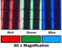
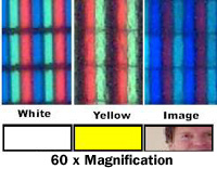
An LCD that can show colors must have three subpixels with red,
green and blue color filters to create each color pixel.
Through the careful control and variation of the voltage applied, the intensity of each subpixel can range over 256 shades. Combining the subpixels produces a possible palette of 16.8 million colors (256 shades of red x 256 shades of green x 256 shades of blue), as shown below. These color displays take an enormous number of transistors. For example, a typical laptop computer supports resolutions up to 1,024x768. If we multiply 1,024 columns by 768 rows by 3 subpixels, we get 2,359,296 transistors etched onto the glass! If there is a problem with any of these transistors, it creates a "bad pixel" on the display. Most active matrix displays have a few bad pixels scattered across the screen.
|
|