4.2 Constructive modeling of historical buildings
The
benefits of using three-dimensional graphics techniques in constructing
models are obvious. First of all, models can be manipulated to provide
multiple viewpoints. Rotating a model can provide a better understanding
of the physical relationships of the components of the actual structure,
as well as the construction techniques involved. Moreover, three-dimensional
models can replicate the actual construction of the building itself, including
features normally hidden to the eye, such as interior bracketing, and the
model can be deconstructed to reveal such hidden features. Images of our
work below on the two Buddhist temple buildings in the Aizu region of Japan
illustrates these benefits.
Golden Hall at Enichiji
The
first structure that we modeled using the AutoCAD AME CSG system
was the Golden Hall at Enichiji, a temple located at the foot of Mt. Bandai.
Although Enichiji was the religious center of the region throughout much
of the Heian period (794-1185), no buildings or images from that period
are extant today. In order to produce a model of the Heian Golden Hall,
the structure that housed the temple's most important Buddha-images, the
authors relied on data introduced in archaeological site reports.16
Figure 4: Structural view
The
construction of the Golden Hall model was a difficult task. At present
the only solid information is the existence of seven foundation stones
for pillars, demarking the north and part of the east walls. A base of
piled stones also stretches along the north and east walls, and remains
of a retaining wall abut the (surmised) southwest corner. This information
has led archaeologists at the site to conclude that the building measured
five bays from east to west and four or five from north to south. We have
constructed the Golden Hall model as a five by four building (Figs. 4 and
5).
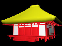
Figure 5: Normal view
In
addition to archaeological data, the model was based on standard temple-building
practices of the eighth and ninth centuries.17 We also took
into consideration the snowy climate of the Aizu region, which dictated
a steeper roof slope than is common in other areas of Japan. In addition,
we consulted Yamagishi Seiji, a master miya daiku (shrine carpenter)
and the scion of an 800-year carpentry tradition in this region.
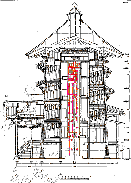
Sazaedô Pagoda
Recently
declared a National Important Cultural Property, Sazaedô, a pagoda
built in 1796 in Aizu-Wakamatsu, is noted for its unique architectural
feature, a double-helical interior walkway that takes visitors from the
front entrance to the top of the structure, then over and down to the back
entrance. The double helical walkway is part of an interior tower (Figs.
6a, b and c). (For more details on the Sazaedô construction, including
black and white reproductions of these figures and some others, see Vilbrandt,
Goodwin, and Goodwin, 1999.18 The drawings in Figs. 6c, 7c,
8c and 9a were adapted from engineering blueprints done in 1965 by Kobayashi
Bunji.)
 |
 |
 |
|
Figure
6a: Interior
tower with image alcoves - wire frame
|
Figure
6b: Interior tower - colorized
|
Figure
6c: Full drawing showing
|
The 3D CAD model can be used to display such components separately, so that the construction may be seen and understood. Even an actual visit to the site does not enable such views.
 |
 |
 |
|
Figure
7a: Exterior
tower with walls added - wire frame
|
Figure
7b: Model
of exterior tower with walls - colorized
|
Figure
7c: Full drawing showing the location of the exterior tower
|
The interior tower is housed
in an exterior tower, with a separate support structure (Figs. 7a, b and
c).
 |
 |
 |
|
Figure
8a: The
exterior tower overhang - wire frame
|
Figure
8b: The
exterior tower overhang - colorized view
|
Figure
8c: Full
drawing showing the location of the exterior overhang
|
The tower exterior shows helical overhangs protecting the windows from direct sunlight (Figs. 8a, b and c).
|
|
|
|
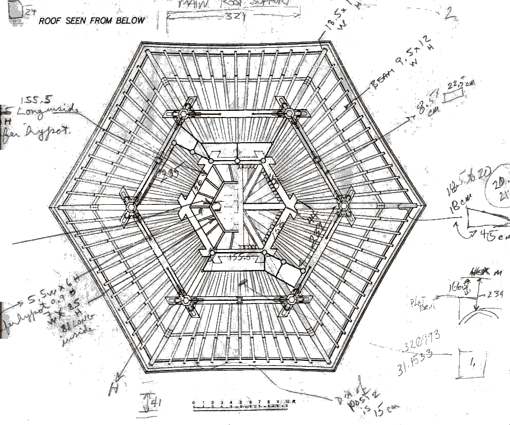
Figure
9a: Roof
- engineering drawing
|
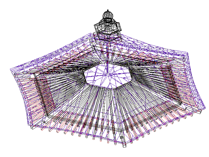
Figure
9b: Roof
- wire frame 3D CAD model
|
 |
 |
|
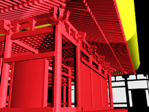
Figure
9c: Roof
- false color CAD Model
|
Figure
9d: Roof
- Rendered 3D CAD model, from below
|
Fig. 9a is an engineering drawing of the roof shown from below. By using measurements from this drawing, and supplementing them with measurements taken on site, a 3D CAD model was constructed, and is displayed in the wire frame view (Fig. 9b) and the rendered views (Figs. 9c and 9d).
The entrance and its canopy
are structures which can be better understood from the model (Figs. 10b,
10c, and 10d) than from a photograph (Fig. 10a) or even from a visit to
the actual site, since they are complex objects and access and sightlines
are restricted.
 |
 |
| Figure 10a: Entrance canopy photograph | Figure
10b: Entrance
canopy – wire frame
CAD model |
 |
 |
| Figure 10c: Entrance canopy rendered | Figure 10d: Entrance canopy – alternate view |
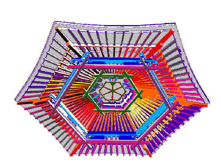
It is possible to select only one section from the single CAD model of the entire structure, and display it from multiple viewpoints and with various levels of detail (Figs. 11a, b and c).
 |
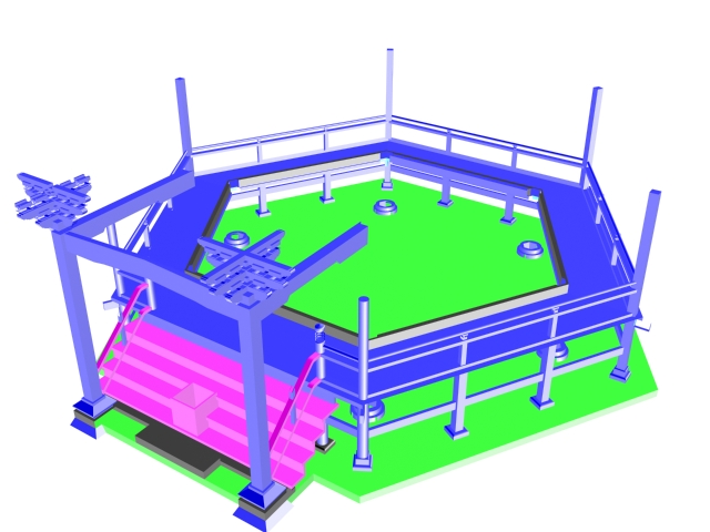 |
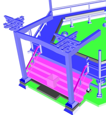 |
| Figure 11a: Wire frame of the base | Figure 11b: Colorized CAD model of the base | Figure 11c: Base – details of the supports |
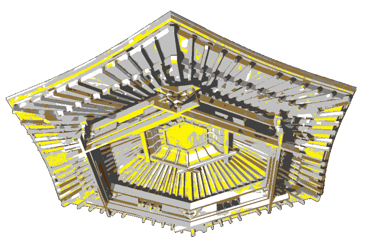
Because of the constructive approach, any part may be rendered without displaying the other components, as shown in (Fig. 11d), and an external shell may be fully rendered (Fig. 11e).
 |
 |
|
Figure
11d: Rendered
model showing helical structure
|
Figure
11e: Fully
rendered view
|
The
models illustrated above are virtual constructions using virtual lumber
cutting, positioning and joining according to the specifications of the
miya daiku based on emperical knolwage of the past. By a virtural
lumber cutting positioning and joining we mean that we create each
piece of temple from virtual parts that represent the shape of each piece
of lumber in the same order, that would have been used by the miya daiku.
The virtural lumber cutting, positionsing and joining empirically shows
the value of digital preservation of cultural heritage using constructive
modeling. The 3D model has recently been used to produce high quality renderings
of the interior of Sazaedô, as would be seen by a person walking
through the structure,19 and to produce QuickTime and AVI movies
of the journey through the temple. We plan to enhance the current model
by including 3D reproductions of the images formerly enshrined in the building.
We also intend to develop VR facilities to allow the examination of these
images independently, and to allow the viewing of parts of the structure
that cannot be accessed in the actual building. See http://ggpl.org/sasa2001/
Virtural Surfaces to Synthetic Objects
The
miya daiku uses specific parts of the tree or piece timber in a
specific place or way. Therefore the timber is saw-milled in a specific
manor and the parts of each piece of timber are noted and used together
to create a "living" harmonious structure. A simple example of this
specific use of timber is that the main columns of the temple are cut from
four sides of the mountain and there orientation to the earth and to each
other on the mountain is maintained in the structure if possible.
With the use of HyperFun representation we can reach beyond the virtual
surfaces of object pasted with inaccurate bit maps that are a poor representation
of the actual object, in the future with weather records and growth
rings of other trees we can synthetically grow a tree using volume
modeling and then create a synthetic piece of timber and using virtual
using the same type of milling procedures and operations create a synthetic
parts and build a synthetic representation of the temples mention above.
The results of the application of volume modeling of mixed materials of
the different densities of wood we call wood grain would create synthetic
trees. Synthetic simulations of the procedures and processes of the
miya daiku would allow us a deeper understanding the past
and would archive not only the historical objects them selfs that hint
of the possilbe processes used, but will allow us to back engeer and archive
the miya daiku's materials, tools and practaces them selfs.